 |
home | products | applications | research | about |
Hydroxy Systems
Although experimenters researching Hydroxy have spent vast amounts of time and energy building plate cells, tube cells, dry cells etc employing a range of techniques including brute force electrolysis, no successful closed system has been demonstrated. The few successful demonstrations of 100% Hydroxy powering small generators have been achieved only by using external AC supply to power the electrolyzer. A high energy plasma spark holds the greatest promise for successful operation of a closed loop lean burn generator running only on Hydroxy. The method of producing high energy plasma discharge by using a high current plasma source across a low impedance path is not new and many patents have been filed over the years and almost all of them have since expired. The working concept of RPG 4700 unit is based on the expired NASA Patent 4122816. Other expired plasma spark patents can be found here in chronological order:
US Patent No. 3788293, US Patent No. 4029072, US Patent No. 4223656, US Patent No. 4366801, US Patent No. 4369756, US Patent No. 4996967.
Although the plasma spark systems have been around for over 30 years there has been a renewed interest in its application to Hydroxy combustion in large part due to the open source energy movement.
However the technological limitations inherent in high frequency capacitor charging applications is the principle stumbling block for adoption of this technology until now as any continuous high energy Plasma system, even at moderately high engine speeds, places a substantial load on the battery, inverter and other charging components making the entire system bulky, inefficient and expensive.
This makes the RPG 4700 an ideal add on Plasma device for use on any Hydroxy system as hydrogen forms an excellent explosive-implosive plasma fuel. In addition to the torque generated by the high energy plasma with just regular gasoline, the energetic spark explodes water mist allowing the combustion of leaner moisture rich Hydroxy fuel mixtures while the excessive air serves to cool the combustion. Indeed it would not be an exaggeration to say that the plasma spark is probably the mission critical component for Hydroxy / alternative fuel lean burn engines.
Stanley Meyer Water Fuel Systems


Plasma cutters work by sending a pressurized gas, such as nitrogen, argon, or oxygen, through a small channel. The center of this channel is the negatively charged electrode, while the nozzle tip is the positive electrode. When power is applied to the negative electrode, a powerful spark is generated between the positive and negative electrodes. The plasma itself conducts electrical current. The cycle of creating the arc is continuous as long as power is supplied to the electrode and the plasma torch stays in contact with the metal that is being cut. In order to control the radius of the plasma beam and regulate the unpredictable nature of plasma, the plasma torch cutter has a second set of channels. These channels release a constant flow of shielding gas around the cutting area. The pressure of this gas flow effectively controls the radius of the plasma beam.
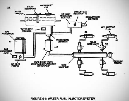
Stanley Meyer states in his Water Fuel Injection System Memo WFC 423 DA (page 103 ~ 104) of Water fuel full data pdf) that his:
"WFC Hydrogen Gas Management System is ideally suited as a retrofit energy system to both reciprocating (rotary piston engine) and turbine jet engines associated with the aviation industry"... 'To ensure proper energy-flame projection and subsequent energy-flame stability, constant displacement water pump causes and allows ionized ambient air gases, noncombustible gases, and water to be displaced under static pressure up to and beyond 125 lbs psi, respectively.'... "Energy-Flame density is enhanced and sustained by causing ionized gases of spray port to be deflected into liquid spray path, together water mist and ionized air gas are, now, directed toward and deflected through non-combustible gas spray path producing uniformed water-fuel mixture. Energy-Flame temperature is regulated by controlling the volume flow-rate of each fluid mediums in direct relationship to applied voltage intensity. To elevate Energy-flame-temperature still further, simply increase fluid-displacement while maintaining or reducing the volume flow rate of non-combustible gases. To lower Energy-flame temperature simply increase the amount of non-combustible gases or reduce the fluid flow rate)uniformly while lowering pulse voltage amplitude. The resultant energy-flame pattern is further maintained by allowing the ignited, compressed, and moving gases to be projected to, pass through and beyond nozzle-port under pressure due to gas expansion caused by thermal gas ignition."
Stan Meyers WFC injection system is remarkably similar to a plasma torch, not only in terms of the actual injector design but right down to the use pressurized fuel gas around 125 psi and the use of shielding gases to focus the plasma beam into the combustion chamber of the internal combustion engine.


A closer study of the WFC memo also reveals the spray distribution disc and spray pattern of Meyers injector design. The shielding gas labeled as non combustible laser primed gas while ionized water mist is the main fuel.
Tesla Impulse Technology

When James Clerk-Maxwell formulated his mathematical descriptions of EM waves, he considered two possible ways: longitudinal electric waves, a phenomenon, which required alternating concentrations of electrostatic field lines and traveled by densified and rarefied pulsation of electrostatic fields necessitating a unidirectional field, one whose vector was fixed. These "electrical soundwaves" were rejected by Maxwell, who concluded that such a condition was impossible to achieve. His second consideration was transverse electromagnetic waves which required the rapid alternation of electrical and magnetic fields along a fixed axis. Space spreading electrical lines would supposedly "bend to and fro" under their own momentum, while radiating away at the speed of light from the alternating source and in 1887, Heinrich Hertz announced that he had discovered transverse electromagnetic waves.
In 1889, Nikola Tesla attempted the reproduction of these Hertzian experiments with absolute rigor in his South 5th Avenue Laboratory and found himself incapable of producing the reported effects. No means however applied would produce the effect which Hertz claimed. In fact Tesla went to Bonn and met Hertz and proved to him his error. Tesla in his article the true wireless gives an account of this trip.
"Ever since the announcement of Maxwell's electro-magnetic theory scientific investigators all the world over had been bent on its experimental verification. They were convinced that it would be done and lived in an atmosphere of eager expectancy, unusually favorable to the reception of any evidence to this end. No wonder then that the publication of Dr. Heinrich Hertz's results caused a thrill as had scarcely ever been experienced before. At that time I was in the midst of pressing work in connection with the commercial introduction of my system of power transmission, but, nevertheless, caught the fire of enthusiasm and fairly burned with desire to behold the miracle with my own eyes. Accordingly, as soon as I had freed myself of these imperative duties and resumed research work in my laboratory on Grand Street, New York, I began, parallel with high frequency alternators, the construction of several forms of apparatus with the object of exploring the field opened up by Dr. Hertz. Recognizing the limitations of the devices he had employed, I concentrated my attention on the production of a powerful induction coil but made no notable progress until a happy inspiration led me to the invention of the oscillation transformer. In the latter part of 1891 I was already so far advanced in the development of this new principle that I had at my disposal means vastly superior to those of the German physicist. All my previous efforts with Rhumkorf coils had left me unconvinced, and in order to settle my doubts I went over the whole ground once more, very carefully, with these improved appliances. Similar phenomena were noted, greatly magnified in intensity, but they were susceptible of a different and more plausible explanation. I considered this so important that in 1892 I went to Bonn, Germany, to confer with Dr. Hertz in regard to my observations. He seemed disappointed to such a degree that I regretted my trip and parted from him sorrowfully. During the succeeding years I made numerous experiments with the same object, but the results were uniformly negative. In 1900, however, after I had evolved a wireless transmitter which enabled me to obtain electro-magnetic activities of many millions of horse-power, I made a last desperate attempt to prove that the disturbances emanating from the oscillator were ether vibrations akin to those of light, but met again with utter failure. For more than eighteen years I have been reading treatises, reports of scientific transactions, and articles on Hertz-wave telegraphy, to keep myself informed, but they have always imprest me like works of fiction."

Tesla's views on Hertzian waves were primarily influenced by his experiments with abrupt and powerful electric discharges, using banks of powerful capacitors charged to very high potentials subsequently discharged through short copper bus bars. The explosive bursts thus obtained produced several phenomena, which deeply impressed Tesla, far exceeding the power of any electrical display he had ever seen.
The abrupt sparks, which he termed "disruptive discharges", were found capable of exploding wires into vapor and propelled very sharp shockwaves, which struck him with great force across the whole front of his body, more like gunshots of extraordinary power than electrical sparks and Tesla was completely absorbed in this new study. These electrical impulses produced effects commonly associated only with lightning. The explosive effects reminded him of similar occurrences observed with high voltage DC generators. A familiar experience among workers and engineers was the simple closing of a switch on a high voltage dynamo which often brought a stinging shock, the assumed result of residual static charging. This hazardous condition only occurred with the sudden application of high voltage DC which resulted in a bright bluish crown of deadly static charge that stood straight out of highly electrified conductors, often seeking ground paths which included workmen and switchboard operators followed by a surge current. After this brief surge, currents flowed smoothly and evenly as designed once the switch was closed. The actual supply was somehow being amplified or transformed. But how?
Though discovered by Tesla in 1889, the preliminary observation of this effect was published after an intensive battery of investigations. The "Dissipation of Electricity", published just prior to Christmas of 1892, is the pivotal Tesla lecture. This is the departure point in which Tesla abandons research and development of high frequency alternating current. Divorcing himself from the field of alternating currents entirely, Tesla began an in depth study of the shockwaves and other effects of IMPULSES. In addition to those physical sensations, Tesla also enlarges upon the "gaseous" aspects associated with the phenomena. He observed that the abruptly charged wires in his experiments projected a strange gaseous stream when immersed in an oil bath.. A phenomenon, which he once thought due entirely to wire-adsorbed gases, he found that the effect could be so continuously produced from a single wire that no volume of ordinary adsorbed gas could supply the flow. Indeed, he was able to produce streams of this kind in oil, which so powerfully projected from charged wire ends that they visibly depressed the oil into a hole, some two inches in depth!
The effects of abrupt static discharge could also be intensified to new and more powerful levels by raising the voltage, quickening the discharge frequency or "make-break " rate, and shortening the actual time of switch closure. Tesla initially employed rotating contact switches to produce his unidirectional impulses however these mechanical impulse systems failed to achieve the greatest possible effects. Tesla subsequently sought a more powerful means "automatic switch" in special electrical arc dischargers using the high voltage output of a DC generator as the power supply, and quenching the arc (spark gap) with a very powerful permanent magnet sitting crosswise to the discharge path.
Tesla found that 'radiant electricity' which could be briefly released using abrupt HV DC impulses could induce powerful electrical effects at a distance. These effects were not alternations, not alternating waves. They were longitudinal waves, composed of successive shocking waves. Objects placed near this device became powerfully electrified, retaining a singular charge sign for many minutes after the magnetic discharger had been deactivated. Tesla found it possible to amplify these single charge effects by a simple asymmetrical alignment of the magnetic discharger and by controlling the rapidity of current blowout in the magnetic DC arc, Tesla released a new spectrum of light-like energies throughout his large gallery space capable of filling rooms and vacuum globes with white light.
Tesla called the combined disrupter and secondary helix a "Transformer". Tesla further discovered that the output voltages were mathematically related to the resistance of turns in the helix. High resistance meant higher voltage maxima. Each transformer had to be "tuned" by adjusting the disrupter to its resonant frequency. Adjustments of arc distance provided this control factor. He began referring to his disrupter line as his special "primary', and to the helical coil placed within the shockzone, as his special "secondary". Once each transformer was tuned to its own special response rate, impulses could flow smoothly through the system like gas flowing in a pipe. This is how the modern version of the 'tesla coil' a very crude replication of Tesla's original study of Radiant electricity came about.
The RPG 4700 can be easily used as a low power tesla coil supply in combination with an ignition coil and PWM driver to simulate rotary spark gaps exceeding 500 hz. Moreover the Plasma output of the RPG 4700 can be wired in parallel to double, triple or quadruple, the capacitance for large tesla coils. We can also build custom Research Radiant plasma generators that will have all the attributes of Tesla's DC spark gap allowing the user to control rate of discharge, energy of discharge, and duration of discharge from 0 to 5 khz.
Pulsed Permanent Magnet Motors
The permanent magnet / pulsed DC electromagnet motor - generator is based upon simple physics that a high school student with a good working knowledge of auto mechanics and basic physics can build
The Pulsed DC Magnet motor - generator consist of two opposing disk, a rotor and a stator. The rotor is connected to a shaft that allows it to rotate. The Rotor has a fixed number of permanent magnets 4, 6, 8 etc arranged equidistant around the circumference of the rotor which faces the stator. The stator is fixed in position next to the rotor but independent of the shaft. Mounted on the stator are an equal number of electromagnets (coils with soft iron core) that are arranged directly opposite the permanent magnets of the rotor.
As the rotor rotates, the permanent magnets come into alignment with the electromagnets. During this phase the permanent magnets are attracted to the iron, steel core of the electromagnets. Torque is provided to the shaft by the magnetic attraction of the permanent magnet and the iron, steel core. No power is consumed. This is the Attraction Phase of the Power Cycle.
As the permanent magnet rotates past the center of the electromagnet, a power pulse is fired through the electromagnet. The like polarity of the electromagnet and the permanent magnet cause the permanent magnet to be repelled. The RPG 4700 in combination with a HV spark trigger such as ignition coil or pulse transformer can be used as the power pulse source. Torque is provided to the shaft by means of the magnetic flux of the permanent magnet and the magnetic field generated by the electromagnet. Power is consumed for only a brief [milliseconds] period of time. The power pulse is delivered at the optimum time for the optimum duration by an infrared laser and photo detector switching system. This is the Repulsion Phase of the Power Cycle. The greater the discharge impulse current of the power pulse, the stronger the torque, making the RPG 4700 ideal for use in such motors as the unit in combination with an ignition coil does not consume more than 38 watts at maximum load.
Most of the work, power delivered to the shaft in the form of torque, is done by the permanent magnets. Because power is consumed for only a brief period of time upon each alignment of the permanent magnet and electromagnet, very little power is necessary to run the motor-generator, making it highly efficient. Pick-up coils wound around the electromagnet utilize the collapsing magnetic field [back EMF] of the power pulse to generate a current that can be employed to recharge secondary batteries while a small DC generator connected to the rotor powers an additional load.

